
Pressure Vessel Baffle Plates: Function, Placement & Design Guidelines for Better Flow Control
By A.S. Engineers & Fabricators Technical Team, 38+ Years, Ambernath MIDC, Maharashtra. Flow control is a major issue in the design and operation of pressure vessels, reactors, heat exchangers, storage equipment, and other process vessels. Uncontrolled fluid flow can lead to uneven distribution, dead zones, excessive turbulence, vibration, erosion, and inefficient heat or mass transfer.
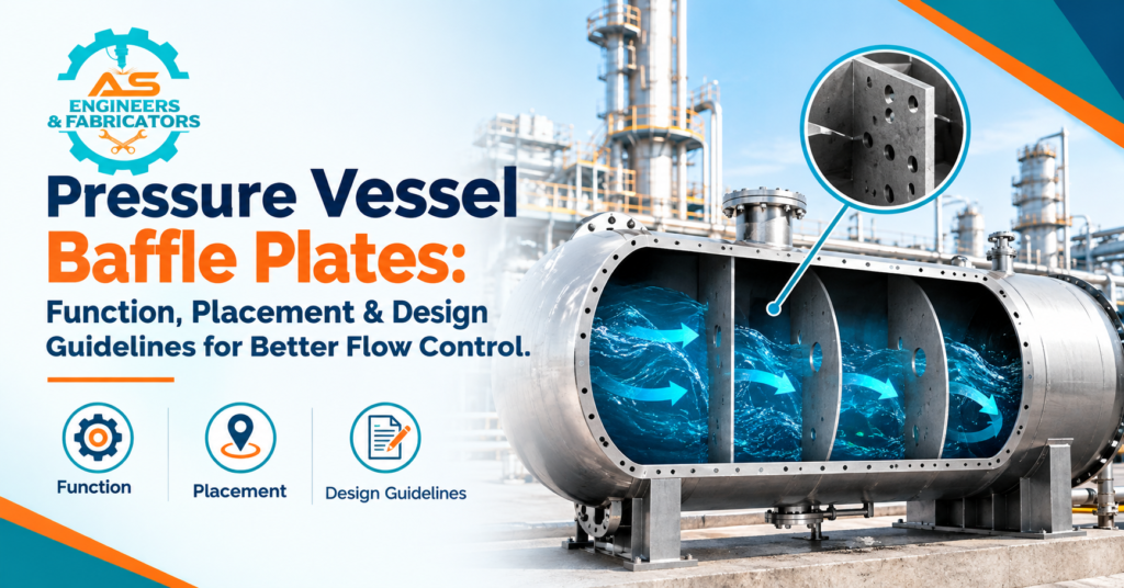
A baffle plate in a pressure vessel is an internal device designed to affect fluid flow within the vessel. Depending on the equipment configuration, baffles can be used to redirect flow, reduce direct impingement, improve mixing, support internal components, or promote more uniform process conditions.
A. S. Manufacturers & Exporters of Customised Industrial Fabrication Components and Pressure-Vessel Equipment, Ambernath MIDC, Maharashtra (ASEFS India). The need for proper pressure vessel baffle plate design guidelines is because the baffle should be able to perform its intended flow-control function as well as be structurally suitable for the vessel operating conditions.
Also Read: Lifting Brackets for Scaffolding: Types, Safety & Applications
What is a baffle plate in a pressure vessel?
A pressure vessel baffle plate is a fabricated internal plate fitted into a pressure vessel or process equipment to control the path and distribution of fluid.
The baffle can be orientated perpendicular to the primary direction of flow, parallel to the primary direction of flow, or at an angle to the primary direction of flow.
The design is dependent on the equipment’s purpose. It can be used for:
Flow deflection
Distribution of flow
Improvement of mixing
Turbulence management
Direct impingement reduction
Increase of heat transfer
Short-circuit flow protection
Internal support of equipment
The specific arrangement of baffles will be determined by the vessel design and process requirements, rather than adopting a universal configuration for all situations.
What is the purpose of baffle plates in pressure vessels?
When fluid enters a vessel, it will not necessarily fill the available space evenly. Depending on the inlet location, vessel geometry, fluid properties, and operating conditions, the flow can favour certain regions. This can decrease process efficiency.
A well-designed baffle can modify the flow path and promote a more orderly motion in the vessel. Pressure Vessel Baffles – Major Roles.
Baffle plates can be used to:
Redirect incoming fluid
Reduce impingement on inlet
Enhance fluid distribution
More mixing.
Minimise stagnant areas
Residence time distribution improvement
Internal equipment support
Shield vessel surfaces from direct high-velocity flow
Improved heat and mass transfer for some selected applications
Actual function depends on vessel process design.
How Does a Baffle Plate Control Flow?
A baffle is a physical barrier or guide within the vessel.
The baffle is designed to direct the fluid flow to change direction or pass through a controlled opening rather than the fluid flowing from the inlet to the outlet.
This can increase the effective flow path through the vessel.
For example, a series of baffles in a horizontal vessel can cause the fluid to flow through successive sections rather than following a relatively direct path from inlet to outlet.
Baffles in mixing equipment may interfere with the circular motion of the fluid, promoting bulk mixing.
Properly configured baffles in heat-transfer equipment can influence the velocity and distribution of fluid across heat-transfer surfaces.
Types of baffle plates in pressure vessels
The baffle arrangement is a function of the vessel geometry and process application.
Full Baffle Plate
A full baffle covers a large area of the vessel cross-section and forces fluid to pass through a defined opening or around the plate.
It can be utilised in cases where a strong flow redirection is needed.
Divisional Baffle
Segmental baffles are cut or open in sections, and fluid flows through the cut or opening.
The opening can be shaped and sized for the desired flow pattern.
Circular Baffle,
Circular baffles may be used in cylindrical equipment where the process requires a particular flow arrangement.
Longitudinal Baffle
Longitudinal baffles are usually positioned parallel to the longitudinal axis of the vessel.
In some vessel configurations, they can split or steer flow.
Baffle Impingement
An impingement baffle can be installed at an inlet to reduce the impact of high velocity on internal surfaces or downstream components.
The design should consider velocity, pressure drop, erosion, material selection, and mechanical loads.
Position of Pressure Vessel Baffle Plate
One of the most important aspects of the design is the placement of baffles.
Improper positioning can lead to unwanted pressure drop, stagnant zones, poor mixing, or ineffective flow distribution.
1. At the Inlet
A flow baffle is a baffle that redirects or distributes flow coming in.
This can be especially true if the incoming fluid is of high velocity or if there is a need to control direct impingement on the wall of the vessel.
2. Between inlet and outflow
Baffles can be fitted between the inlet and outlet to increase the flow path and improve distribution.
The spacing and opening arrangement should be decided as per the process requirement.
3. On Surfaces of Heat Transfer
When heat transfer is a factor in equipment, baffles may be installed to direct fluid across the heat-transfer surfaces.
The purpose might be to enhance flow distribution and heat-transfer performance while managing pressure drop.
4. In Mixing Vessels
Baffles are vertical strips that interrupt rotational flow created by an agitator.
Without baffles, fluid can tend to swirl around the vessel rather than mixing efficiently throughout the volume of the vessel.
5. Near Sensitive Internal Parts
If the process design demands it, a baffle can also be installed to shield internal components from direct fluid impact.
Guidelines for Baffle Plate Design in Pressure Vessels
Fluid dynamics and mechanical integrity should be considered in designing a baffle.
The following guidelines for the design of pressure vessel baffle plates offer a general engineering framework.
1. Know the Process Conditions
The first step is to set the operating conditions.
The important parameters are:
Fluid Type
Density of Fluid
Viscosity of
Flowrate
Betriebsdruck [1]
Working Temperature
Pressures of Design
Design Temperature
Corrosiveity
Content-rich
Gaseous or liquid phase
Minimum Residence Time
These conditions affect the baffle material, size, thickness, opening arrangement, and support system.
2. Identify the Desired Flow Pattern
The baffle should be designed to fit the desired flow pattern.
Here are some questions to ponder:
Do we need to change the course?
Does it have to be mixed?
Does the direct impingement bug you?
Does it have to be evenly distributed?
Does residence time matter?
Does heat transfer occur?
Good or bad turbulence?
A baffle should be designed to meet a specific process requirement, not just to deflect the flow.
3. Pressure Drop Consideration
A baffle causes resistance to fluid movement.
If the opening is too small or too many baffles are installed, the pressure drop can increase significantly.
Excessive pressure drop can:
Increased pumping requirements
Reduced system efficiencies
Affects downstream equipment
Rising operating expenses
Modify planned operating parameters
Thus the geometry of the baffles should provide flow control with acceptable pressure loss.
4. Choose the Right Baffle Opening
The flow pattern is highly dependent on the size and location of the opening.
A smaller opening can lead to greater flow restriction and altered velocity distribution.
A larger opening can reduce restriction but may give reduced flow redirection.
The right configuration is based on process calculations and vessel geometry.
5. Mechanical Strength Testing
During operation, a baffle plate is exposed to fluid forces.
The plate is subject to:
Differential pressure
Fluid collision
Vibrations
Thermal expansion
Dynamic loads
Stress Localised
Therefore, the plate thickness and support arrangement shall be designed in accordance with the applicable engineering requirements.
6. Think about Baffle Supports
Structural supports may be required for large or heavily loaded baffles.
Support arrangements may consist of:
supporting bracket
structural beams
Sections
Stiffeners,
Welded brackets.
Internal structural elements
The support system shall be so designed that it will withstand the loads expected during operation without endangering the vessel shell or internals.
7. Consider Thermal Expansion
Large temperature swings may occur in pressure vessels.
Baffle plates and vessel shells can expand at different rates, depending on the choice of material and geometry.
Where applicable, design should therefore allow for thermal movement.
Excessive restriction of thermal movement can add to the stress in the baffle or its supports.
8. Select Appropriate Materials
Baffle material must be compatible with the process atmosphere.
Common materials include:
Carbon Steel (CS)
304 Stainless Steel
316 Stainless Steel
316L Stainless Steel
Duplex Stainless Steels
Low-alloy steels
Speciality Alloys
Material selection is determined by:
Resistance to corrosion
Temperature (C)
Anxiety
Fluid process
Strength (Mechanical)
Conditions of Erosion
Welding Specifications
Very corrosive services may require stainless steel or special alloys.
9. Look at Corrosion Allowance
If corrosion is anticipated, the design may require a suitable corrosion allowance.
The allowance required is dependent upon the process medium, material, and expected service conditions.
In severe corrosion environments, it may be more appropriate to select a corrosion-resistant material rather than to depend only on additional thickness.
10. Assess Erosion
The erosion of high-velocity fluids with abrasive particles can occur.
Baffles located directly in the flow path can experience considerable wear.
Design considerations can be:
Flowrate
Concentration of particles
Particle size
Hardness of materials
Geometry of surfaces
Substitutability
Where erosion is a factor, the baffle may need to be of a suitable material, thicker, wear-protected, or replaceable.
Mixing Vessel Baffle Plates
Baffles are especially important in many mixing applications.
If an agitator is rotating in an unbaffled vessel, the liquid may tend to swirl around the vessel.
This can lead to:
Weak vertical mixing
Formation of surface vortices
Lower mixing efficiency
Irregular Concentration
Poor process uniformity
Vertical baffles may interfere with this rotational motion and achieve better mixing.
The number, width, location, clearance, and thickness of baffles are dictated by the vessel geometry, the agitator configuration, the fluid properties, and the process objective.
Baffle Plates in Heat Exchangers
Baffles are also important in different heat-exchanger arrangements.
They can guide fluid over heat-transfer surfaces and affect the velocity distribution.
Well-designed baffles can help:
Better fluid distribution
More turbulence.
Enhance heat transfer
Reduced bypass flow
Where applicable, provide tube support in equipment.
But throttle it down too much, and you increase the pressure drop.
Heat-transfer performance and pressure-drop requirements must therefore be considered together.
Inlet Jet Impingement Plates
Inlet Impingement Baffle: Used to control high-velocity flow entering a vessel.
Direct inlet flow can lead to:
Localised erosion
Heavy turbulence
Liquid entrainment
Internal component damage.
Spread out unevenly
An impingement baffle may deflect the incoming stream and reduce direct impact.
Its size, location, and support should be based on actual inlet conditions and vessel design.
Typical Applications of Pressure Vessel Baffle Plates
Baffles for pressure vessels are common in many industrial systems.
Chemical Processing Industry
Baffles may be used in chemical reactors and process vessels to mix and distribute flow.
Petrochemical Facilities
Baffles are useful in process vessels where flow and separation need to be controlled.
Oil & Gas
Internal baffles for process equipment can perform flow management, inlet protection, and separation functions.
Water purification
Some process tanks and vessels have internal plates to improve fluid distribution and residence time.
Pharma Industry
Baffles may be used in mixing vessels to enhance process uniformity.
Fertiliser Plants
Process vessels used for chemicals and gases may have internal baffles, depending on the design of the equipment.
Power plants
Baffles are used in equipment handling water, steam, cooling systems, and heat-transfer operations.
Processing food
Materials and hygienic designs can be used for suitable food processing applications if chosen appropriately.
Manufacturing of Pressure Vessel Baffle Plate
Manufacturing accuracy is important because the finished baffle must fit correctly inside the vessel and remain in its designed position. A possible process of fabrication may comprise.
Material Inspection
The raw material is checked against the required material specification.
Cutting the Plate
The plate is cut to the approved dimensions and drawings.
Edge Preparation and Machining
Necessary holes, slots, cut-outs, edges, and mounting features are made ready.
Where Required Forming
Some baffle designs may need to be bent or formed.
Welding
Welding of supports, stiffeners, or attachments shall be in accordance with approved fabrication requirements.
Dimensional Inspection
We check dimensions, openings, flatness, and mounting features.
Surface Inspection
The last part is checked for visible damage and surface condition.
Final Verification
The baffle shall be checked against the approved drawing and project requirements prior to installation or dispatch.
Quality Control for Baffles in Pressure Vessels
Quality control helps to guarantee the baffle is made to the required design.
Inspection may consist of:
Inspection of Raw Material
Traceability of Materials
Inspection – Dimensional
Measurement of Thickness
Weld examination
Inspection of Surface
NDT as needed
Inspection of Fit-Up
Final Quality Control
The requirements for inspection of pressure-vessel projects shall be in accordance with the applicable design code, customer specification, material standard, and project documentation.
ASEFS India Pressure Vessel Manufacturing Capabilities
A.S. Engineers & Fabricators (ASEFS India) is a custom fabrication provider for pressure vessels and industrial process equipment.
With over 38 years of experience in engineering and fabrication, ASEFS India undertakes project-specific equipment and fabricated components as per drawings, specifications, and operating requirements.
Manufacturing and supply of ASEFS India’s products include:
Pressure vessel
Industrial Storage Tank
Heads, Spherical
Ends Dish Clad
Reactor Vessel
Components of a Heat Exchanger
Baffle Plates
Elements of the Internal Vessel
Heavy Steel Construction
Industrial Processing Equipment
Material and methods of fabrication are determined by the demands of the project.
Why Should You Choose ASEFS India for Baffle Plate Fabrication?
ASEFS India brings engineering experience, heavy fabrication, and custom manufacturing to the table.
Key strengths are:
38+ Years of Engineering Experience
Manufacturing Facility at Ambernath MIDC
Specialised Fabrication
Manufacture of Pressure Vessels
Internal Parts Manufacturing
Cutting of Plates
Welding & Fabrication
Traceability of Material
Quality Control
Manufacturing for the Project
Manufacturing (Export Orientated)
Baffle plates are manufactured in accordance with customer drawings, dimensions, material specifications, and equipment requirements.
Related ASEFS India Products & Services
ASEFS India also manufactures & supplies.
Pressure Vessels
Storage Tanks
Dish Heads / Dish Ends
Ellipsoidal Heads
Dish End Clad
Expansion Joints
Rubber-lined tanks & pipes
Industrial Gratings
Anti-Vortex Plates
Heavy Steel Structures
Steel plant machinery
These products are used in applications in the chemical processing, petrochemical, oil & gas, fertiliser, steel, power generation, water treatment, and other industrial sectors.
Connect with ASEFS India
A.S. Engineers & Fabricators (ASEFS India)
Manufacturing Plant:
Plot No. W-108/1, Anand Nagar, MIDC Ambernath East, Thane – 421506, Maharashtra, India.
WhatsApp: +91 92267 69978
Email: info@asefsindia.com
Catalogue: ASEFS India Product Catalogue
Also Read: Top Dish End Manufacturers in India: Quality, Standards & Pricing
Conclusion
A well-designed pressure vessel baffle plate can be very important in controlling fluid movement, improving distribution, reducing direct impingement, supporting mixing, and influencing heat-transfer performance.
The correct baffle configuration is determined by the geometry of the vessel, fluid properties, flow rate, pressure, temperature, material compatibility, acceptable pressure drop, mechanical loads, and process objectives.
Design rules for pressure vessel baffle plates have been developed so that the flow control requirements are met without sacrificing the structural integrity and long life of service. Design considerations include baffle thickness, opening size and location, supports, material selection, corrosion allowance, erosion resistance, and thermal movement.
A. S. Engineers & Fabricators ASEFS India has over 38 years of experience in engineering and fabrication. It manufactures customised pressure vessels, baffle plates, dish ends, internal components, storage tanks, and other industrial fabrication solutions from its Ambernath MIDC facility in Maharashtra.
FAQ
1. What is the function of a baffle plate in a pressure vessel?
Ans: A baffle plate for a pressure vessel is used to control and direct fluid flow in a vessel. Depending on the application, it can improve distribution, mixing, residence time, heat transfer, or inlet-flow management.
2. Where are baffle plates placed in pressure vessels?
Ans: Baffle plates can be placed near vessel inlets, between inlet and outlet zones, around heat-transfer surfaces, or inside mixing vessels. Where it is located exactly is determined by the process and equipment design.
3. How to design a pressure vessel baffle plate? What are the considerations?
Ans: Important parameters include flow rate, fluid properties, pressure, temperature, vessel shape, allowable pressure drop, mechanical loads, material compatibility, corrosion, erosion, and the required flow pattern.
4. What is the material for pressure vessel baffle plates?
Ans: Typical materials are carbon steels, stainless steels 304, stainless steels 316 / 316L, low-alloy steels, duplex stainless steels, and special alloys. The choice of material is a function of the process conditions.
5. Do baffles affect pressure drop?
Ans: Yes. The size, number, spacing and design of the openings in baffles can influence the pressure drop as baffles create resistance to fluid flow.
Recent Posts
-
 Best Dish End Shapes for Corrosion-Resistant Tanks and Reactors
 -
 Propane Storage Tank Manufacturing: Standards, Safety Features & Buying Guide
 -
Pressure Vessel Baffle Plates: Function, Placement & Design Guidelines for Better Flow Control
-
 Why Delrin (Acetal) Machine Parts Outperform Metal Components in Wear Applications
 -
 Delrin Sprocket Gears vs Delrin Spur Gears: Which One Fits Your Machine Design?
 -
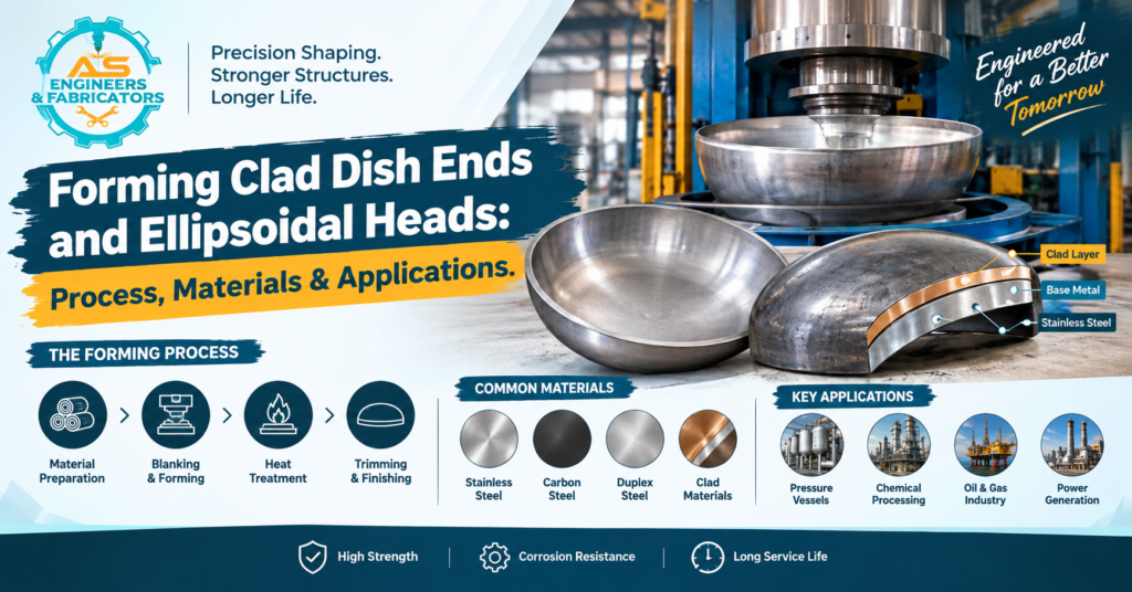 Forming Clad Dish Ends and Ellipsoidal Heads: Process, Materials & Applications
 -
 ASEFS India and Russia’s Industrial Machinery Sector: Solutions, Expertise and Opportunities
 -
 How ASEFS India Contributes to Singapore’s Industrial Machinery and Equipment Sector
 -
 Construction Indonesia 2026: Connecting Global Construction and Engineering Companies with Indonesia’s Infrastructure Market
 -
 AUTOMEX Penang 2026: Connecting Global Automation Companies with Malaysia’s Smart Manufacturing Industry
 -
 Vietnam Industrial Automation Fiesta (VIAF) 2026: Connecting Global Engineering Companies with Vietnam’s Smart Manufacturing Industry
 -
 Why Air Manifolds Improve Compressed Air Distribution in Manufacturing Plants
 -
 How to Choose the Right Air Receiver Tank for Industrial Applications
 -
 Why Rubber Expansion Bellows Are Used in Water Treatment and Chemical Plants
 -
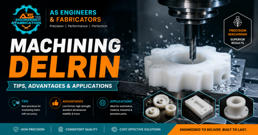 Machining Delrin: Tips, Advantages & Applications

At A.S. Engineers & Fabricators, our team excels in designing, manufacturing, and erecting steel structures that set industry benchmarks. We have established a robust presence in metal fabrication, heavy equipment, and steel structures, providing top-tier solutions for industrial plants and high-rise buildings.